Welcome to the new ESIP website!
DIY sensing: anatomy of an analog sensor

Overview
This tutorial will demonstrate how to program an embedded device to read data from an analog sensor. We will cover some of the basics of analog sensing, such as analog-to-digital conversion, as well as the nuts-and-bolts of programming an embedded device. While this lesson is tailored specifically for the Cypress PSoC hardware and software toolchain, the lessons learned in this tutorial can easily be carried over to other popular platforms, like Arduino.
Getting started
For this tutorial, you'll need the following materials:
– An analog sensor
– Male-to-male Jumper wires (x3)
– A Cypress PSoC microcontroller
– The PSoC Creator software (Windows only)
For the sensor, we will be using a Maxbotix ultrasonic range finder, which senses the distance to an object using acoustic pulses. This sensor operates over the same voltage range as the board, making it easy to work with. However, if you don't have this sensor, do not worry! Any analog sensor that operates between 0 and 5V will work (including sensors that operate on the 2.7/3.3V range). If you don't want to buy any sensors, you can even use a battery instead.
Note: If you want to use a battery, use the following wiring when you get to the hookup section of this tutorial: connect the negative end of the battery to ground, and the positive end of the battery to the analog signal wire.
For the microcontroller, you can use any Cypress PSoC 5LP device. The cheapest option (~$10) is the Cypress PSoC5LP Prototyping Kit, which includes an onboard programmer (negating the need for a programmer cable).
Analog to Digital Converters (ADCs)
Before we can start programming, we'll need some background on analog-to-digital converters. Digital computers like the PSoC 5LP can't interpret analog signals directly. Rather, these signals must be first converted into a stream of binary bits that a computer can understand. An analog-to-digital converter accomplishes this task by transforming an analog electronic signal into a digital signal.
Types of ADCs
The PSoC provides two types of ADCs.
– Successive Approximation (SAR) ADCs (2 available simultaneously)
– Delta-Sigma ADC (1 available)
Successive Approximation (SAR) ADC
The SAR ADC uses a digital-to-analog converter (DAC) to approximate an analog input signal.

The SAR ADC works as follows:
– First, a controller tells the N-Bit DAC to generate an output voltage.
– The output of the DAC is then compared to V_in using a voltage comparator. This tells us if the initial guess is too high or too low.
– The controller then adjusts the output of the DAC and guesses again.
– This is repeated until V_in is found.
Pros:
– Lower cost than Flash ADC
– Can be built for high-resolution applications.
Cons:
– Slower speed at high accuracies due to the need to compare many values.
Delta-Sigma ADC

The Delta-Sigma ADC is based on a delta modulator—a feedback control system that produces an output signal from an input signal. The feedback path contains an integrator, which integrates the output signal to create a feedback signal x̂(t). The feedback signal is subtracted from the input signal x(t) to generate an error signal e(t) = x(t) - x̂(t). The error signal is fed into a voltage comparator, which compares the error signal to GND (0 V) and produces an output signal y(t), which is either V_ref or -V_ref.
The Delta-Sigma ADC works as follows:
– First, from the analog signal an estimate x̂(t) is subtracted to calculate an error signal e(t) = x(t) - x̂(t).
– The error is fed into a 1-bit voltage comparator (quantizer) which outputs:
y(t) =  V_ref, e(t) ≥ 0
y(t) = -V_ref, e(t) < 0
– This tracks the input signal.
– The accuracy depends on V_ref and the sampling time dt.
Pros:
– Very high resolution
– Almost completely digital
Cons:
– Can be slow if oversampled
Reading an analog sensor
Having covered the basics of analog-to-digital conversion, we are now ready to integrate the analog sensor into our embedded platform. First, we'll wire up all the components. Then, we will implement the hardware components in the device firmware using a schematic. Finally, we will write a driver (in the C language), which tells the microcontroller how to take readings from the analog sensor.
Connecting the sensor
First, we need to physically connect the sensor to our embedded device.
– Connect the black GND (Pin 7) wire on the sensor to a GND wire terminal on the board.
– Connect the green Analog (Pin 3) wire on the Sensor to the P3[2] wire terminal on the board.
– Connect the red V+ (Pin 6) wire on the sensor to the P3[3] wire terminal on the board.
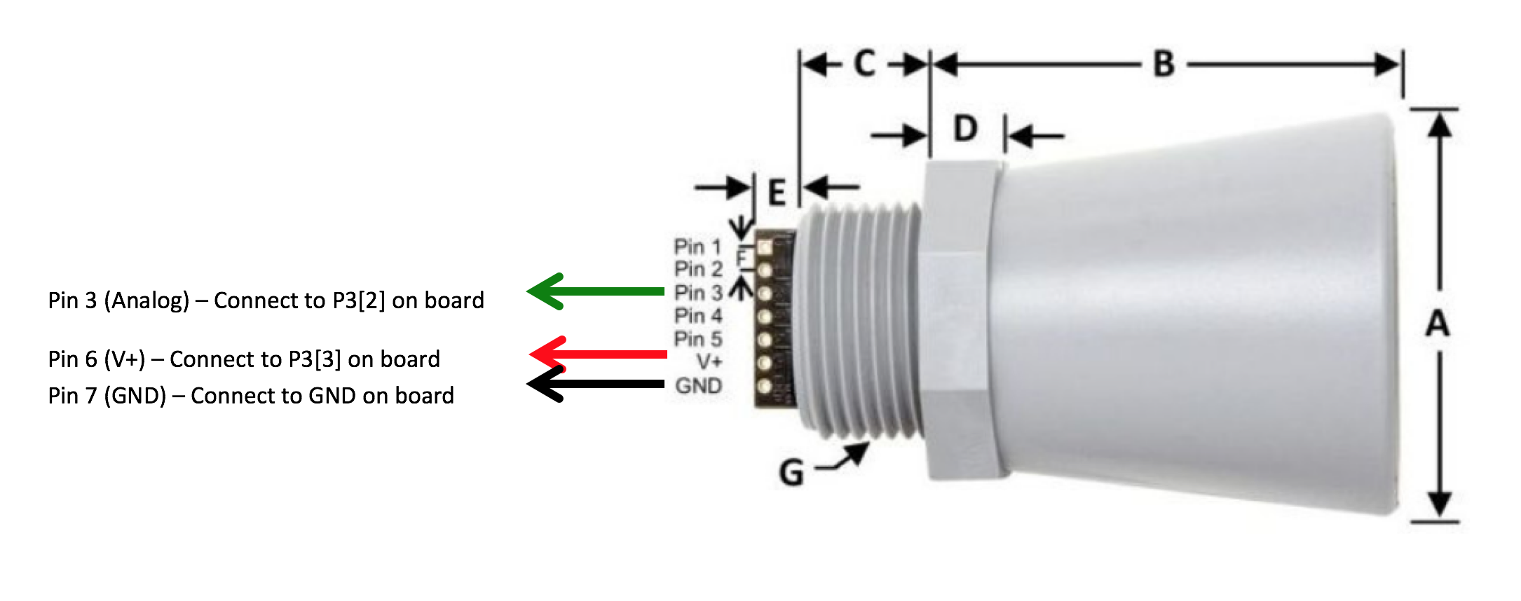
Note: your wire colors may differ. If they do, please ignore the color directions and just use the pin connection information. Using a flat-head screwdriver, place the wires from the ultrasonic sensor in the clamps and tighten.
The red and black wires provide power to the sensor and the green wire outputs the analog signal. The sensor uses a 5V power source. Make sure the power jumper on the board is set to 5V.
Placing components
Next, we'll begin implementing hardware components using an easy-to-understand schematic. Open up the PSoC Creator program on your computer. Start a project in PSoC creator called `analog-sensor`. Now open up the device schematic (.cysch) file.
Power pin
First, we will place a power pin that can turn the sensor on or off. In the case of the board used in this tutorial, the V+, or voltage inputs on your breakout board are equipped with PMOS switches. These switches are connected to one of the PSoC’s pins. When the pin is flipped high (logic 0), the switch will not deliver power to the sensor. Alternatively, when flipped low (logic 1), the switch will deliver power to the sensor. To use this feature, we can just simply drag and drop a digital output pin component to the schematic.
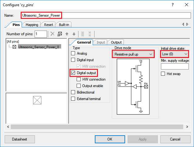
– Place a Digital Output Pin on your schematic. Call this pin Ultrasonic_Sensor_Power, and Remove the Hardware Connection option.
To make sure the sensor starts in the OFF (which requires a digital high) condition we must set the initial state to Low (0).
– Under the General tab, set the Drive Mode to Resistive Pull Up, and the Initial state to Low (0).
Analog to Digital Converters
The PSoC has three analog-to-digital converters (ADCs), each of which can be used simultaneously for making analog measurements:
– Two 12 bit Successive Approximation (SAR) ADCs: While accurate, these ADCs are specifically designed for rapid measurements.
– One adjustable 20 bit Delta Sigma ADC: A 20 bit, ultra-low noise ADC. The accuracy is adjustable, from 8 to 20 bits, with lower resolutions corresponding to higher sampling rates.
Note: For advanced applications requiring many analog sensors, the above ADCs can be multiplexed to permit for many analog sensors to be sampled.
– In the schematic view, drag and drop the SAR ADC component onto your schematic. The component is located in the Analog -> ADC folder in the component view.
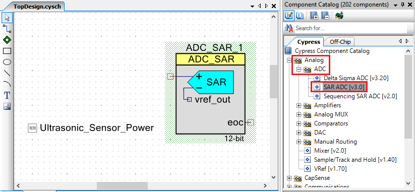
– Double click the ADC_SAR_1 component on your schematic to adjust its settings.
– One of the fundamental settings of an ADC is its Input Mode. The input mode can either be single ended or differential.
– The maxbotix depth sensor has only a single signal wire. So we will use we will use the Single input mode.
– Looking at the sensor datasheet for the MaxBotix Distance sensor, we can see the output signal can vary between 0-5V. We thus need to make sure that the ADC range is set in a way to capture this range in sensor output.
We will use most of the default configuration but make sure the following settings are applied:
– Resolution: 12 Bits
– Input Range: 0.0 to 2.048V (Single Ended) 0 to Vref*2

Note: This sensor can also be configured to run in digital mode using the RS232 connection. This can be easily configured on the board, but we’ll stick the analog output for this tutorial.
Note: If you do not have this sensor available, you can just measure the voltage of an AA battery as a substitute using the same settings.
Note: Single ended inputs are a voltage difference between the signal wire and the ground wire 0-X volts. A differential input has two signal wires, one connected to the positive ADC input, and the other to the negative ADC input. This gives a range that does not necessarily start at zero, and can even potentially begin negative (–X volts to Y volts). Depending on the sensor you are using, reading the datasheet will likely inform you of the correct input mode.
Hooking up pins
The SAR ADC in single-ended mode requires only one input. In your schematic, drag and drop Pins and Ports -> Analog Pin components and connect it to the SAR ADC using the Wire Tool. Name this pin Ultrasonic_Analog_Signal by double clicking it.
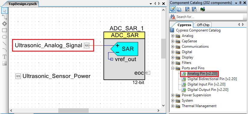
Ensure that the analog pin has the following settings:
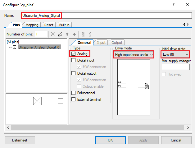
Assigning Pins
– Open analog-sensor.cydwr.
– Set Ultrasonic_Sensor_Power to P3[3].
– Set Ultrasonic_Analog_Signal to P3[2].
Writing the sensor driver
The sensor just outputs a voltage, which we measure using the ADC. To get the actual distance, we have to convert this reading. The datasheet specifies that “the HRXL-MaxSonar-WRS sensors use a scale factor of (Vcc/5120) per 1-mm.” If we read the voltage, we can then get the distance in mm using the following formula:
distance = voltage_reading * (resolution / voltage_range);
Create a file called analog.c that contains the following code:
#include <project.h>
#include <stdlib.h>
#include "analog.h"

#define MAXBOTIX_V_RANGE 4.75
#define MAXBOTIX_RESOLUTION 5120

int take_analog_depth_reading(){
    // Initialize variables
    int16 adc_result = 0;
    float volt_reading = 0;
    int distance = -9999;

    // Initialize and start ADC
    ADC_SAR_1_Wakeup();
    ADC_SAR_1_Start();
    ADC_SAR_1_StartConvert();

    // Turn on sensor and delay briefly to let it settle
    Ultrasonic_Sensor_Power_Write(1u);
    CyDelay(500u);

    // If ADC has finished converting, get the result
    adc_result = ADC_SAR_1_GetResult16();
    // Convert the raw ADC reading to volts
    volt_reading = ADC_SAR_1_CountsTo_Volts(adc_result);
    distance = volt_reading * (MAXBOTIX_RESOLUTION / MAXBOTIX_V_RANGE);

    // Turn off sensor
    Ultrasonic_Sensor_Power_Write(0u);

    // Stop ADC conversion
    ADC_SAR_1_StopConvert();
    ADC_SAR_1_Sleep();

    return distance;
}

/* [] END OF FILE */
Now create a file called analog.h that contains the following code:
int take_analog_depth_reading();

/* [] END OF FILE */
Finally, edit the existing `main.c` file:
#include <project.h>
#include "analog.h"

// Initialize variables
int depth_analog = -9999;  // Analog depth reading


int main(void)
{
    // Enable global interrupts
    CyGlobalIntEnable;

    for(;;)
    {

        // Take distance reading
        depth_analog = take_analog_depth_reading();

        // Delay 1 second
        CyDelay(1000u);
    }
}

/* [] END OF FILE */
Code Explanation
This driver performs the following main tasks: (i) starts up the ADC, (ii) takes a reading using the ADC and then converts it to the proper units, (iii) stops the ADC.
The project.h file must be included to use function calls from Cypress's built-in-components (including the pins and the ADC). If you are familiar with C programing, you may have also noticed that we included stdlib.h to support string operations.
Note: Header files, those ending in
".h", allow for the use of functions already written by others. By including the header file at the of your main.c file, you are able to call functions described inside the file. For example,stdio.hallows us to usesprintf()to format our strings.
The ADC must be started and told to begin making measurements. This is done by calling the ADC_Start() and ADC_StartConvert() functions.
Note:
ADC_Wakeup()is used to restore device configuration after sleep mode, whileADC_Sleep()is used to store ADC configuration settings before sleep mode. In this example, these functions are not needed.
We then enter a never-ending for loop, taking an ADC sample and saving it to a variable depth_analog. We then pause for one second before repeating the same step. The measurement is actually taken by the take_analog_depth_reading() function, which we have declared for this purpose. The function returns the ADC reading value when the measurement has been completed. The first step is to provide power to the sensor, which is done by calling Ultrasonic_Sensor_Power_Write(1u). We then delay the code for 100 milliseconds to give the sensor time to settle.
To read the ADC measurement, we call the ADC_SAR_1_GetResult16() function. This function will return an integer value, ranging from 0 to 2^N, where N is the number of bits (or resolution) of the ADC. What’s actually more useful in this case is the Voltage of the ADC measurement, as opposed to the integer value. Luckily, the API provides us with a simple conversion. By calling ADC_SAR_1_CountsTo_Volts(), we can convert the integer value to a floating point voltage value.
Note: The API also supports methods to make conversions to milli-, and micro-volts. To learn more, read the datasheet for the ADC component.
We then take this reading and plug it into the sensor calibration equation mentioned earlier to obtain the distance.
Testing the driver
In the PSoC Creator program, Build the project to compile the drivers. Now, set a breakpoint at the line containing CyDelay(1000u); in main.c. Next, select Debug in the toolbar to run the firmware in debug mode. The current sensor reading can be read by hovering your mouse over the depth_analog variable. Try running through several iterations, and see if the sensor reading matches the actual distance from the sensor to the nearest object.
And that's it! You've programmed your first analog sensor.
For more tutorials on programming embedded devices for environmental sensing, visit open-storm.org